Robotic Beam Assembly & Welding Systems
The same model-driven assembly and welding workflow, with one difference: crane-assisted manual repositioning or operator-initiated integrated beam rotation between setups.
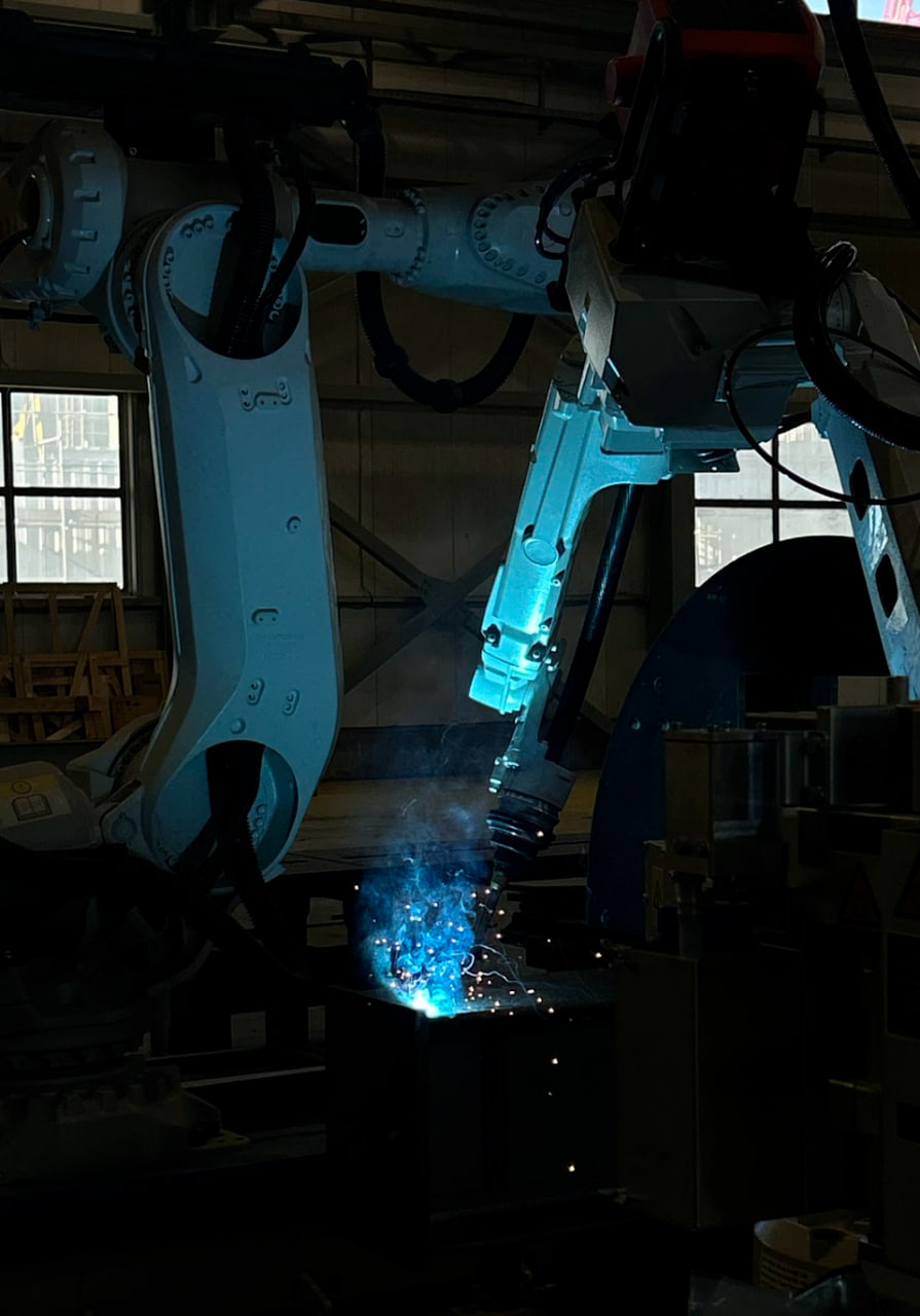
Robotic cell QUANT STEELFAB 360
Model-driven beam assembly and welding with operator-initiated integrated rotation between setups
Explore Robotic cell QUANT STEELFAB 360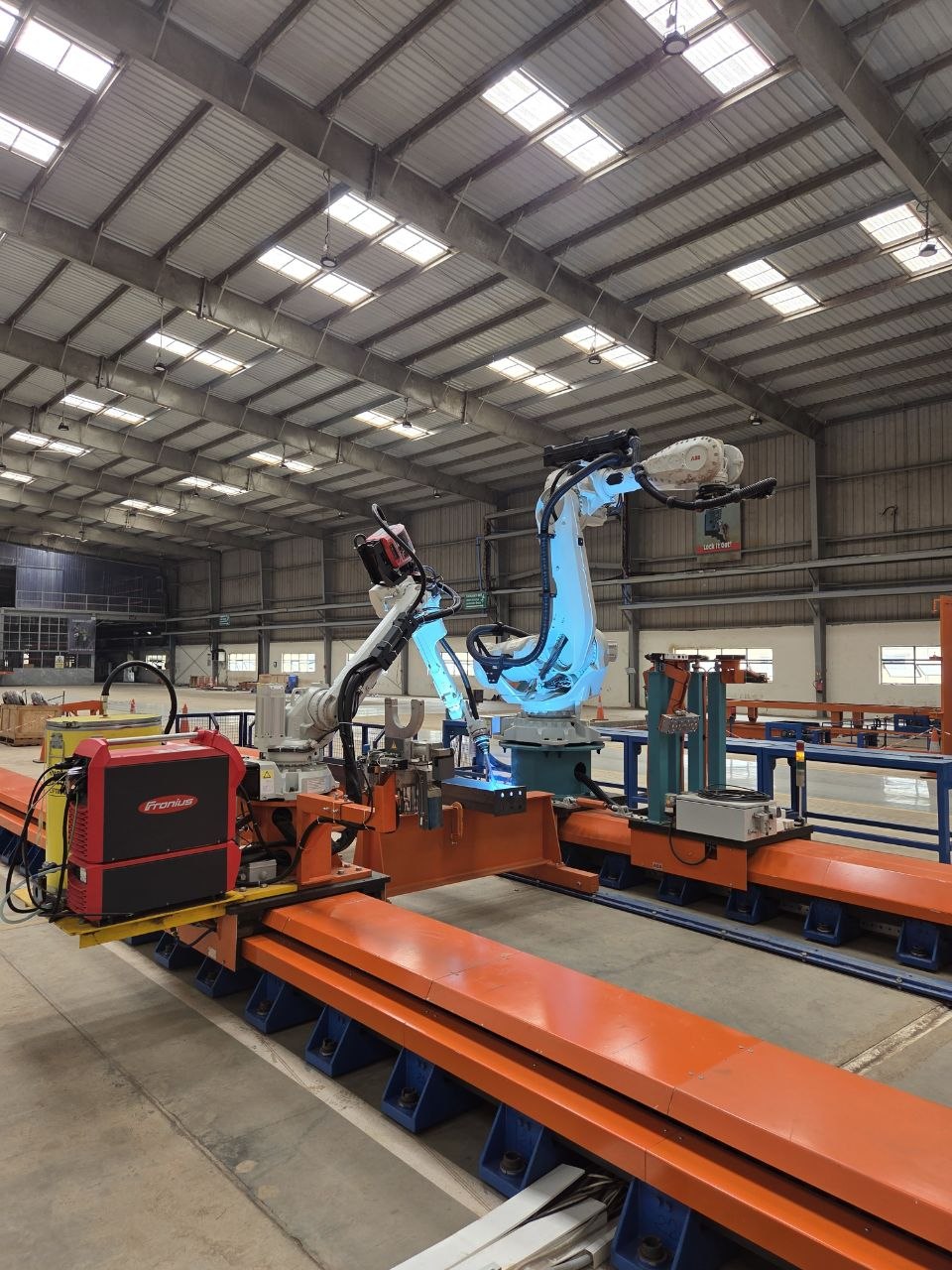
Robotic cell QUANT STEELFAB
Model-driven beam assembly and welding with software-guided, crane-assisted setup changes
Explore Robotic cell QUANT STEELFABCompare QUANT STEELFAB Systems
Both systems share job preparation, measurement, assembly, and welding capabilities. The setup change is different. Final scope, output, footprint, utilities, and investment are reviewed against the beam portfolio and site constraints.
| Decision factor | QUANT STEELFAB | QUANT STEELFAB 360 |
|---|---|---|
| Job preparation | Tekla engineer selects beams; Quant plugin exports production data; Quant software simulates the job. | Same model-driven workflow. |
| Geometry and parts | Scanner measures the beam and scans the parts tables once at the start of the job; missing parts and thickness mismatches are reported. | Same measurement and parts checks. |
| Assembly coordinates | Software calculates the transformation; the operator reviews the color-coded match and selects Continue before coordinates are sent to the robot. | Same calculation and operator review. |
| Assembly and welding | Robotic fit-up, tack welding, and finish welding for supported parts within the current setup. | Same robotic operations. |
| Weld location | TouchSense before welding; no continuous seam tracking during the welding pass. | Same TouchSense workflow. |
| Next setup | The software shows the beam and holders in the next setup. The operator releases the clamps, turns the beam with an overhead crane, checks its X/Y position, reclamps it, and confirms the setup in the software. Crane availability can affect the changeover. | The operator selects Next setup in the software. The integrated rotator then moves the beam to the angle required for that setup. This replaces crane-assisted turning between setups; loading, unloading, supervision, and application checks remain part of the workshop process. |
| Beam size and mass | 3,000–12,000 mm standard length; up to 14,000 mm with extended tracks as a project option. Maximum beam mass: 6 tonnes. | Same size range and option. Maximum beam mass: 6 tonnes, including the integrated-rotator configuration. |
| Application review | Beam geometry, component mix, weld access, workshop layout, and crane requirements. | Same application review, including rotator suitability for the selected beams. |
From Feasibility Review to Site Acceptance
International delivery is scoped project by project. The review establishes responsibilities and acceptance criteria before commercial commitment.
1. Feasibility
Review representative Tekla models, beam geometry, connection types, weld requirements, product mix, and target output.
2. Site & Safety Review
Confirm layout, material flow, lifting strategy, utilities, extraction, guarding, electrical standards, and target-market requirements.
3. FAT & SAT Plan
Define factory and site acceptance tests, reference parts, documentation, training, and measurable pass criteria.
4. Service Scope
Agree commissioning, remote support, warranty, preventive maintenance, and critical spare-parts responsibilities for the destination.